
Design
First Attempt
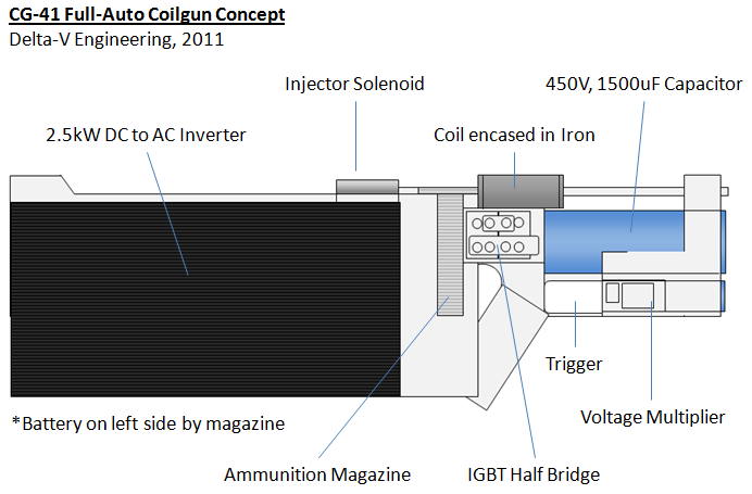
The full-auto coilgun project started in November 2010, and the initial design was a high-voltage, single-stage, capacitor driven coilgun I called the CG-41. I hoped to achieve a muzzle energy of about 7.5 Joules with a Rate of Fire (ROF) of 4 Rounds Per Second (RPS). However, the design disintegrated around the charging circuit, which was a monstrous 2.5kW DC-AC inverter meant to power appliances from a car battery. The inverter was gigantic, heavy, and had a number of electrical issues that prevented it from being readily integrated into the coilgun design. As the design exploded in size and complexity to accommodate the charging circuit while still failing to work properly, it had to be abandoned during the testing phase in June 2011.
 First Attempt: The CG-41 Concept
The Full-Auto Coilgun: An Engineering Problem
Here’s the problem: A single-stage coilgun has a distance of one coil-length over which to accelerate the projectile. If the projectile is to be accelerated to a significant speed over this very short distance, a very high electrical current is necessary, and a high voltage capacitor bank is needed to provide this current. This high voltage-capacitor bank typically needs several seconds to recharge between shots, and this is out of the question when you want your gun to fire many rounds per second. You can try to skirt this problem with a super-high power rapid charging circuit, but this is impractical and inefficient for a portable design, as I learned from the failed CG-41.
An alternate option is to remove the capacitors and directly power the coil from high-current batteries. This solves the long recharge time problem, but introduces another problem: even the best portable batteries can only supply a few hundred amps, so the battery-powered coil is very weak and barely tosses the projectile. But there is a solution! If many battery-powered coils are lined up down a long barrel and fired one-at-a-time as the projectile passes through, the small contribution from each coil adds up to provide a large muzzle energy to the projectile, without needing any capacitors!
This solves the full-auto coilgun problem. It also seriously improves the efficiency of the gun compared to single-stage designs since the low current coils consume much less charge from the batteries while still providing a high muzzle energy to the projectile. This also conveniently eliminates the cost, weight, complexity, power loss, and safety problems associated with the high-voltage capacitor bank and charging circuitry. A totally new design is now in order- a portable, massively multistaged, battery driven, full-auto coilgun!
Requirements
The first step is to decide what I want my coilgun to accomplish. The design process should then focus on meeting these requirements in the simplest, most direct manner possible.
- Smashing Power: Muzzle energy of at least 10J
- Full-Auto: At least 10 RPS
- Portable: Length less than 58cm (length of CG-33)
- Maintainable: All parts accessible for repair or replacement
- Cool Looking: No tape, cardboard, wood, or colorful plastic used in construction
The Maths
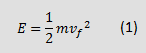
Typically, coilgunners start their design by multiplying the capacitor energy equation by a predicted efficiency factor η to see how much stored energy they will need to produce muzzle energy E.
![]()
However, since this gun won’t use capacitors, that won’t work. By using nothing but three simple kinematic equations, an equally dumb but equally useful back-of-the envelope muzzle energy equation can be derived for a battery driven coilgun.
![]()
![]()
Where t is time and d is distance over which average power P is required to accelerate a projectile of mass m from initial velocity vi to final velocity vf. Note that equation 3 assumes constant acceleration, which is a close approximation with a highly multi-staged coilgun. Begin by eliminating t by feeding equation 3 into equation 2 and re-arranging to solve for E.
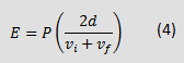 Assume vi=0 since the projectile is motionless at the beginning of the shot, and use equation 1 to eliminate vf.
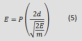 Re-arranging to solve for E, we arrive at the final rough formula for muzzle energy of a battery-driven coilgun:
 The most frequent comment I get on my coilguns is that I should use a lighter projectile to improve performance. This equations shows why that suggestion is wrong. It’s counter-intuitive, but for a fixed power and distance (e.g. fixed capacitor bank and coil), a lighter projectile will gain less muzzle energy than a heavier one. This equation will now be used to guide the design process.
Projectile
Every part of a coilgun, from the power supply to the coils, is designed based on the properties of the projectile. First I need to decide what muzzle velocity I want. I’d like the CG-42 to shoot at least as fast as the CG-33, which has a muzzle velocity of 40m/s. With my 10J muzzle energy requirement and equation 1, that means the projectile should have a mass of 12.5g. Steel nails make great projectiles since they’re cheep, quick to machine, and have decent magnetic properties. I happened to have a pile of 6.5mm diameter nails left over from a home improvement project. If I cut them to 50mm lengths and sharpen them down, they come out to 12.3g which is close enough!
Steel Nails Make Nice Projectiles
Number of Coils
To get the best possible efficiency, I want to chose the longest possible acceleration distance and divide this length into as many coils as possible. This reduces the power needed to reach the required muzzle energy. Balancing this is the fact that each stage must be accompanied by a set of switching hardware and circuitry, which quickly becomes expensive and difficult to fit inside a portable design when the number of stages becomes too high. Based on the length of my projectile and the maximum length requirement of the gun, I found that 8 stages could be practically fitted into the design.
Batteries
The next thing to choose is the batteries. I begin by re-arranging equation 6 above to solve for the coilgun’s power requirement.
I already have E and m from the previous steps. For the eight 50mm coils and an equally sized 50mm projectile, this results in d=8x0.05m=0.4m. Thus, the projectile will need to be supplied with about 500 Watts to meet the muzzle energy requirement.
Next, I need to guess the total (battery to projectile) efficiency of my coilgun. Based on other multi-staged, battery-driven coilguns, I might hope for an overall efficiency between 6 and 10%. That means that the batteries must be able to supply somewhere between 5,000 and 8,300 Watts.
When it comes to portable batteries, Lithium Polymer (LiPo) cells are at the forefront of technology (at least in terms of what a hobbyist can afford). LiPo cells come with burst-current ratings of up to 100C (100 times capacity in amp-hours) in packs with up to six cells in series (6S) having a maximum voltage of 25.2V. These battery packs are available with capacities of 2500mAh, 3600mAh, and 5000mAh. Any of these battery choices meet the power requirements with good margin.
For efficient transmission of power to the projectile, the coils must maximize magnetic force exerted on the projectile. Force on the projectile is proportional to coil current multiplied by turns of wire, so the batteries must have high enough voltage to push lots of current through a coil with many of turns of wire. For this reason, I chose to use two 6S batteries in series for a total of 50.4V. I settled on 3600mAh packs in order to ensure that plenty of power was available to the coils and that lots of shots can be fired before the batteries need to be recharged.

Power Supply, iCharger 106b Balance Charger, Venom Racing 22.2V, 6S 3600mAh 50C Li-Polymer Battery Packs
Switches
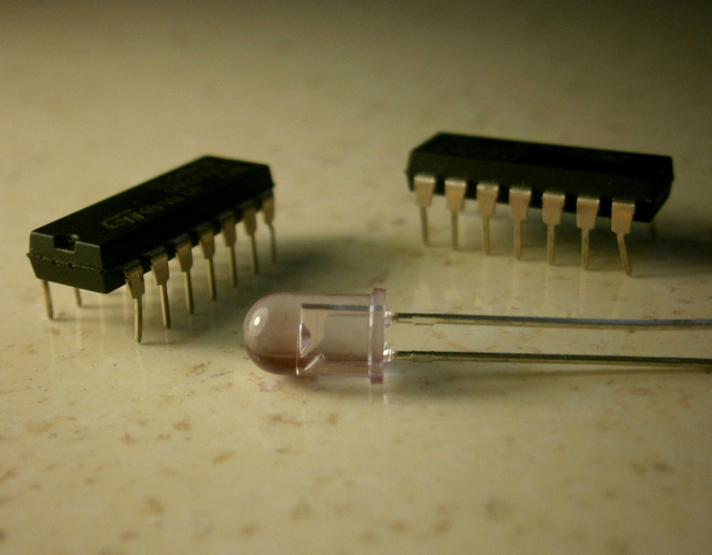
The capabilities of the switch will determine the maximum current the coils must be designed to draw. Since this design will use the same coil for each stage (see coil section) each stage can also use the same switch. For this design, an SCR will not work since SCRs require the current to fall to zero in order to switch off, which won’t happen with batteries. I had several IGBTs left over from the CG-41 which should work nicely. They can pass current pulses up to 300A, and come in a compact ISOTOP package with screw terminals which make them easy to attach to bus bars and low gauge wires.

Box of IGBTs
Now the various losses must be considered to ensure that enough power will be delivered to the coils. I estimated that the batteries and interconnecting wires will add about 40mΩ of resistance in series with the coils. Additionally, the IGBTs will dissipate about 900W when they conduct a full 300A. That leaves P = (300A*50.4V – 0.04Ω*300A^2 – 900W) = 10,620W still delivered to the coils. This satisfies the 5,000-8,300W power estimate with a good margin to allow for any variations.
Lastly, note that MOSFETs with the same current rating would operate with about half the power loss of these IGBTs, but the higher voltage rating of the IGBTs will allow me to turn the coils off more quickly, reducing the “suck-back” effect and improving efficiency (see voltage suppression section).
Barrel
For a coilgun, the main purpose of the barrel is to protect the inside of the coils from being damaged by the projectile as it’s pulled through. The main criteria for choosing the barrel is that it should fit the projectile closely and have the thinnest walls possible. When the coilgun is energized, the projectile and coil are linked as a magnetic circuit. Any space between the projectile and coil occupied by non-magnetic material acts like a fat resistor on that circuit and limits transmission of power from coil to projectile. Thus a thin, tight barrel reduces the amount of plastic and air between the coil and projectile and improves efficiency. A metal barrel is ideal because of its thin walls, but the energized coils will generate eddy currents in the metal material due to its conductivity. The power wasted in these eddy currents can be significant and detract from the coilgun’s efficiency. Cutting a length-wise slot down the barrel can mitigate eddy currents, but I don’t have the tooling to accomplish this. For the barrel of the CG-42, I chose a low-friction Teflon tube that fit the projectile nicely.
Coils
For a sensor triggered coilgun like this one (see coil triggering) the inductance of each coil stage does not need to vary to account for the increasing speed of the projectile, so each stage can use the same coil design. The physical dimensions of the coil are already dictated by the dimensions of the projectile and a maximum outer radius I set to limit the physical size of the gun. I then designed a coil that would fit within that space while having as many turns of wire as possible to maximize magnetic force and draw a peak current of 300 Amps from the batteries. I chose to use low-gauge copper magnet wire, which minimizes resistivity and wasted space within the coil dimensions.

Copper Magnet Wire
Voltage Suppression
The coil is an inductor, and an inductor stores energy in its magnetic field. When an inductor is removed from its power supply, the inductor uses its stored energy to generate a voltage that tries to keep the current flowing. If I were to simply switch off the coils at the appropriate time, the coil inductance would generate a voltage spike that could easily exceed the maximum voltage rating of the IGBTs and destroy them. The solution is to suppress the voltage spike by giving the inductor energy somewhere else to go. This is commonly done by connecting a diode anti-parallel to the coil. When the IGBT shuts off the current, the diode begins to conduct and allows the current to circulate in the coil where it decays and dissipates as heat. This switch-off current must dissipate quickly; any current remaining in the coil after the projectile passes the center point will slow the projectile down. The time it takes to to dissipate this current can be significantly reduced by adding a resistor in series with the diode. Each coil in the CG-42 uses a rectifier diode with a high surge current rating and a high-power resistor to quickly dissipate coil switch-off currents.
Magnetic Flux Augmentation
Flux augmentation is the practice of encasing the coils within some magnetic material in order to reduce the reluctance of the magnetic circuit and improve the magnetic linkage between the projectile and coil. Research suggests that ferrous end caps can give a significant performance boost to low power coils such as the ones I’m planning to build. Higher power coilguns can saturate the end cap’s finite ability to be magnetized, making the efficiency boost less significant.
 Iron powder and epoxy used to form coil end caps
To determine the usefulness of end caps to the CG-42 project, I’ll make a rough comparison of magnetic field strength between my coil and the one used in the research. The research setup involved a coil of 40mΩ and 23uH, and a 33,000uF capacitor bank charged up to 60V. This would result in an average discharge current of 472A. The equation for magnetic field strength at the center of an ideal coil is B=μ0*N*I/L where μ0 is the magnetic constant of 1.257×10⁻⁶ T*m/A, N is number of turns, I is current and L is length of the coil. The research coil had 70 turns and was 27mm long. This results in an average field strength of 1.54 Teslas. The same equation applied to the CG-42 coil gives an average field strength of 1.23 Teslas. If the research coil of higher field strength gained a significant performance boost from the end caps, then I should also be able to see a similar performance boost if I build end caps of similar composition.
Coil Triggering
It’s important to have feedback when switching the coils in a multistaged coilgun. If the switching mechanism isn’t adaptive, a small irregularity in one stage introduces a timing error that amplifies in subsequent stages. As the batteries drain with repeated shots and as the coils heat up, the coils will carry less current and produce less acceleration. Thus a timing sequence that is optimized for room temperature coils and a fresh battery will not work well for hot coils or a partially drained battery. The timing of the coils must adapt actively to all possible situations.
Accomplishing this is easier than it sounds. A simple IR sensor can be placed at the entrance of each coil, such that the projectile blocks the sensor as it enters the coil, and clears the sensor as the projectile aligns with the center of the coil (if projectile and coil are the same length). A circuit can trigger the coil as long as the sensor is blocked. This results in near-perfect timing, every time. This implemented for the CG-42 with a simple circuit that only uses a small handful of analog components.
Projectile Feed System
The only moving parts required for this design are in the mechanism that feeds projectiles into the coils. The simplest approach I could think of was to store the projectiles in a spring-loaded box magazine (like a typical automatic weapon) and punch the projectiles out of the magazine at the top via an off-the-shelf “injector” solenoid. The solenoid is spring-loaded, so it pulls itself back to the starting position after being fired to allow another projectile in the magazine to slide up for the next shot. Most coilguns that use a solenoid feed mechanism place the solenoid immediately behind the magazine. However, that eats up precious length that could otherwise be occupied by more coils, so I chose to place the solenoid above the magazine and equip it with a small “arm” that reaches down to push the projectiles out of the magazine.
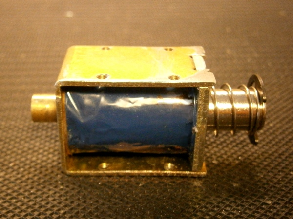
Spring-Return Solenoid
After the mechanical design was completed, I designed a circuit that controls the injector and allows the user to chose semi or full-auto mode. The circuit also sets the maximum rate-of-fire, and reads a signal from the 8th stage trigger to ensure that only one shot is fired at a time.
Power Supply:
The triggering and injector control circuitry require a low, stable voltage to operate properly. The 25V available from the battery packs is too much, so the power supply must step-down the battery voltage to something more usable. There are two options to perform a DC step-down. The first is a linear regulator- a cheap, simple device that shunts the unused voltage as waste heat, which is wasteful with high step-down ratios. The second option is a buck converter, an Integrated Circuit (IC) that drives an inductor and a diode to reduce the voltage. I made the decision that the improved efficiency was worth it, and designed two buck converters- one to power the control circuitry and a second to power a targeting laser.
Also, LiPo batteries can be damaged if drained below 3V per cell (or ~18V total for a 6 cell pack), so a low-voltage detector for each battery was designed into the power supply. It’s a simple circuit that lights a red LED when the battery drops below 18V.
Lastly, two green LEDs were added to the power supply to serve as indicators, one lights when the buck converter is switched on enabling the control circuitry, and another lights when the high-side battery is plugged in and the coils become powered.
Gun Frame
The frame of the gun should be strong, lightweight, compact and easy to build. Minimizing the number of parts, cuts, and bends in the design will save days of effort and frustration when it comes time to build it. I designed the frame of the CG-42 to be built with inexpensive, readily available aluminum bars and sheets joined together with machine screws and epoxy. For the aluminum sheets, I chose alloy 3003 because of its formability and machineability. I’m working entirely with hand tools so I needed to use an alloy that was easy to cut, drill, and bend by hand.
The only high-voltage parts in the whole design are the IGBTs, which can reach up to 600V when fired. I chose to group all of the IGBTs and switching electronics together inside an ABS plastic compartment along the top of the gun to improve the electrical safety of the design. The connections between the batteries and the coils were designed with thick, tightly connected conductors to minimize parasitic impedance that reduces power transmission from batteries to coils. I chose copper bus bars to conduct current to the coils and super-low gauge copper automotive wire to connect the batteries to the bus bars.
The look of whole design started with a simple sketch which then became a scale drawing. Then the design was adjusted and components were rearranged again and again until everything fit inside.

Original Sketch of CG-42 Concept (June 2011).
 Scale Drawing of CG-42 Gun Frame