
Design
I started this project in June of 2008 with almost no experience in electrical and mechanical engineering (other than two disposable camera coilguns that helped me learn some safety practices). The design process was guided by learning from other people’s projects, as I knew very little about the physics involved at the time. I was inspired by a few YouTube videos of monster bench-top coilguns that could punch through metal cans and smash household objects. This project began with an idea: How cool would it be if someone fit that kind of power into a handheld design?
The Design Begins
First I decided that I wanted at least one kilojoule of stored energy, and I found a website selling 3900uF, 400V capacitors for only $15/ea. Four of these would add to a total of 1.25kJ of stored energy. I purchased these capacitors and they made it into the final design. For the capacitor charging circuit, I initially chose Uzzors2k’s 15W Boost Converter (which my friend built for me) and I bought a 12V, 4200mAh NiMH Airsoft battery to power the whole thing. Triggering the gun by touching two wires together, like my disposable camera coilguns, would end in disaster for a coilgun with this much stored energy. The easiest and most effective trigger option was a Silicon Controlled Rectifier (SCR)– a high-current semiconductor switch. I purchased a massive C185N SCR (capable of passing a 3,500 amp current pulse), which also made it into the final design, and two NTE5991 rectifier diodes to protect the capacitors from reverse-voltage at the end of a shot, which were later discarded. Lastly, I bought an LED voltage meter from eBay to display the capacitor voltage. I drew a very crude gun body to be built with plywood, wooden 2x4s and a PVC pipe and called it the CG-31 (the first version of my third coilgun).
Drawing of CG-31 Layout
I kludged together a testbed with a hastily constructed four-inch long coil with three layers of 15AWG wire around a 1-inch PVC pipe, then cut and shaped a projectile out of a steel spike. Barry’s RLC Simulator predicted that this arrangement would result in a critically damped capacitor discharge with a peak of around 1,000 amps into the coil- far from ideal, but okay for testing purposes.
 Setup for First Test Shot
The first test shot occurred on November 1st, 2008 and had mixed results. The boost converter only charged the capacitors to about 100V. Unsure of what would happen, I loaded the projectile part-way into the coil, hid behind the workbench, and touched a wire to a couple AA batteries to trigger the SCR. The projectile scooted out of the barrel and fell to the garage floor. This seems anticlimactic, but it was a triumphant moment since it was the first working test shot of a coilgun that I had built from scratch. Unfortunately, I didn’t know that I should have disconnected the battery and boost converter from the capacitor bank before triggering the shot, and both shorted through the coil and SCR. Wires melted and the boost converter was fried. Lacking the know-how to solder another boost converter, I moved on and built most of the wooden gun frame. Shortly thereafter, an intense junior year of college followed and the project was shelved for some time.
 CG-31 Gun Frame
The Design Revisited
At some point during my junior year, I was inspired to return to my coilgun project. I didn’t know enough about circuits to solder together a new boost converter, so I considered using a car AC adapter and a voltage multiplier as the charging circuit. That proved to be unsuccessful because I couldn’t figure those circuits out either. Eventually I gained some experience building circuits in my control systems class, so I decided that I would build a new boost converter on a breadboard. I also decided to redesign the physical layout of the gun. My experience in engineering school had drastically improved my perspective as an engineer, and I realized that the old wooden design was over-sized and poorly thought out. One day, when I was daydreaming during a boring lecture for the same controls systems class, I sketched out a more compact, plastic design. This turned into a diagram which I named the CG-32.
 CG-32 Layout Concept
Note that I also added some voltage regulators to provide the low voltages needed by the SCR trigger and the voltage meter. These replaced the AA batteries used in the old design. In retrospect there are some obvious shortcomings to this layout- like the long wires that would have to run from the SCR in the back of the gun to the coil in the front, but it was a massive improvement from the CG-31.
To recommence the testing effort, I bought a cheap card table and converted the back of my college apartment into a coilgun workshop. Fortunately, my roommates were also advocates of science so they supported this addition to our living room. I built the boost-converter on a small proto-board, and wired up the capacitor bank. I found that the boost converter didn’t perform well when the battery was below 11V- this is what caused it to charge the capacitors to only ~100V in my previous attempt. For the first time, I successfully charged the capacitors to a full 400V. However, it took way too long, with a best time of 61.2 seconds. I tried two boost converters in parallel with only a small improvement to 54.0 seconds.
Eventually, I decided to switch to Uzzors2k’s 50W Capacitor Charger, which previously scared me with its apparent complexity. With the 50W circuit, I discovered that I no longer needed the capacitor reverse-voltage protection diodes, since the output of the charger is a diode bridge which performs the same function. To handle the high switch-off current, I chose a GBPC4010 rectifier that could handle a pulse of 400 amps. Then I finally bought a soldering iron and soldered the circuit together, and wound the transformer on a flyback core I purchased from eBay.
The Workshop at 627 Stanford
Much to my surprise, it worked the first time, but only charged the capacitors to around 100V with a fully charged battery. I found my mistake- I neglected to place a small piece of plastic between the two halves of the transformer core to establish a tiny yet critical air-gap. I unwound the transformer, added the air-gap, and rewound it again- a tedious process that took hours to complete. I could now charge the bank to the full 400V, but it still took too long- 43 seconds, falling far short of the 50 Watt performance that the design promised. Also, the circuit drew enough current from the battery to blow a 12 Amp fuse, meaning it was chugging at least 144W and putting out only 27W. I didn’t understand how the circuit worked, so I spent much time that summer rewinding the transformer secondary (high voltage side) over and over again, and trying different inductors and tank capacitors to no avail. Senior year of college began and the project had to be shelved once more.
The Design Evolves
Much later that year, things with school and life calmed down and I was able to get back to the project. I replaced the tired 12V battery with a computer Power Supply Unit (PSU) that I converted into a bench-top supply to make testing easier and more consistent.
Computer PSU Converted into Cost-Effective Bench Supply
Then I tried doubling the number of turns on the transformer’s primary (low voltage) side. This was a success and I was able to give the bank a full charge in 29 seconds without blowing any fuses. Then, once again while daydreaming during a boring lecture, I randomly thought to revisit the physical layout of the CG-32 which hadn’t been touched since the previous summer. I drew a rough sketch of the most compact design I could think of that would fit all of the coilgun’s components.

CG-33 Drawing
The new layout didn’t waste any space, so every component was measured and carefully incorporated into a scale drawing. I also had to buy a smaller 12V, 2000mAh NiMH Airsoft Battery to fit into the new design.
Testing
I wired all of the components together on the testbed with a new, more thoughtfully designed coil. This coil used thicker, 12AWG wire and was the same length as the projectile (66mm), an attribute that other coilgun designers have had the most success with. I wound three layers, each with about 33 turns around the plastic barrel from an old M16 Airsoft gun that fit perfectly around the projectile. According to Barry’s Simulators, it would draw about 4.2kA at the peak of the discharge, and the pulse would be about 2.7ms long.
The first full-power test shot occurred in March of 2010 and was a memorable experience. I charged the capacitors, hid behind the sofa, warned my roommates to stay out of the living room, and touched two wires to trigger the SCR. The coil made a clicking noise, immediately followed by a WHACK as the projectile smacked into the ballistic shielding on the other side of the room, penetrating two layers of corrugated cardboard and punching clear through a sheet of ¼ inch plywood. The project’s goal of providing smashing power from a portable design was achieved, and all that was left was to build it into a gun!
 Testbed for First Full-Power Tests and Final Coilgun Design
It quickly became apparent that the smashing power should be exploited in a more entertaining way. My roommate grabbed his old alarm clock, and we placed it about 4 feet in front of the barrel. We took cover and I triggered another shot. But this time, the coil’s click was followed by the sound of breaking glass. The recoil had caused the coil to come loose from its tape-based restraint, sending the projectile over the target and through the window on the other side of the living room, leaving a bullet hole in the single-pane glass. Fearing eviction, I prepared an elaborate yet true story about my engineering project and a “malfunctioning linear motor” in order to baffle the apartment management into not understanding what was happening on their property. But they didn’t ask questions and repaired the window free-of-charge in what is now remembered as a great victory for science.
In the following months, I tested some different coils, including a two-layer coil of the same length and a two-layer coil that was about 1.3 projectile lengths. Neither gave good results, so I stuck with the original 3 layer, 99-turn coil.
Circuit Diagram
Sometime after the completion of the CG-33 I put together this circuit diagram to show how simple the coilgun circuit really is. For details on the charging circuit, see Uzzors2k’s website.
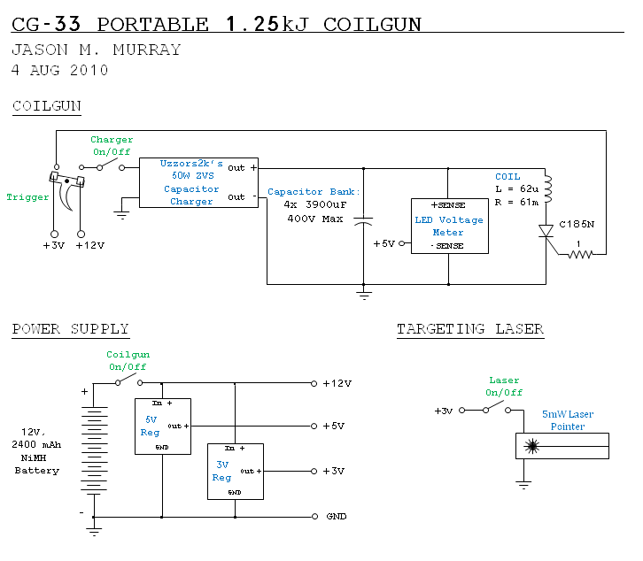
CG-33 Circuit Diagram